Contents
Introduction
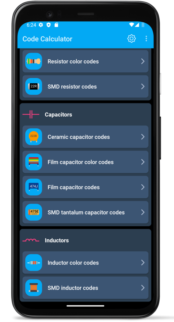
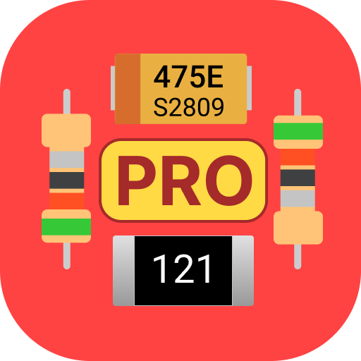
Application for reading codes for resistance, capacitance and inductance of electronic components.
|
|
|
The Application checks the entered value against E-series E6, E12, E24, E48, E96, E192, depending on the accuracy.
Pro versions
Pro version of this application not contains ads and it is not collect any user data.
|
|
|
Application also contains help and detailed description for all codes of electronic components and lists of standard values for E series.

Features
This application supported following features:
- Resistor color codes
- SMD resistor codes
- EIA-96 resistor codes
- Ceramic capacitor codes
- Film capacitor codes
- Tantalum capacitor color codes
- SMD tantalum capacitor codes
- Inductor color codes
- SMD inductor color codes
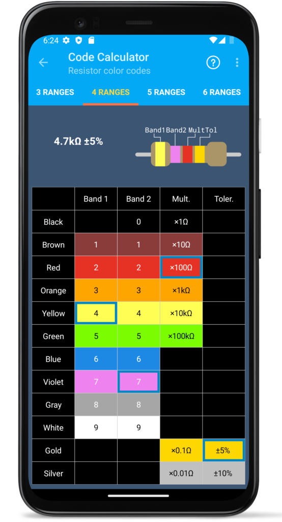
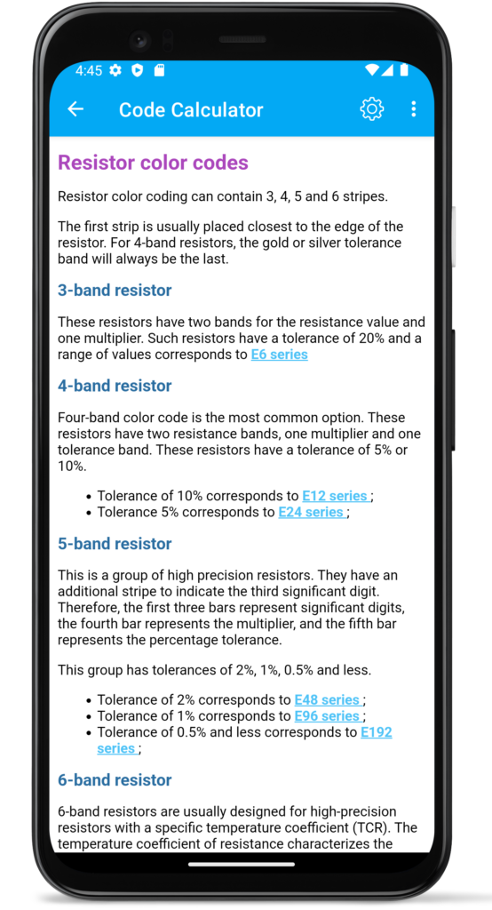
Resistor color codes
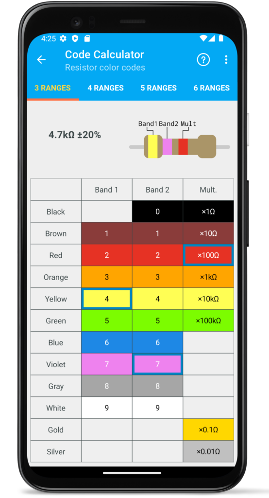
Resistor color codes page contains calculator for 3, 4, 5, 6 ranges resistors:
Resistor color coding can contain 3, 4, 5 and 6 stripes.
The first strip is usually placed closest to the edge of the resistor. For example, on 4-band resistors, the gold or silver tolerance band will always be the last.
3-band resistor
These resistors have two bands for the resistance value and one multiplier. Such resistors have a tolerance of 20% and a range of values corresponds to E6 series.
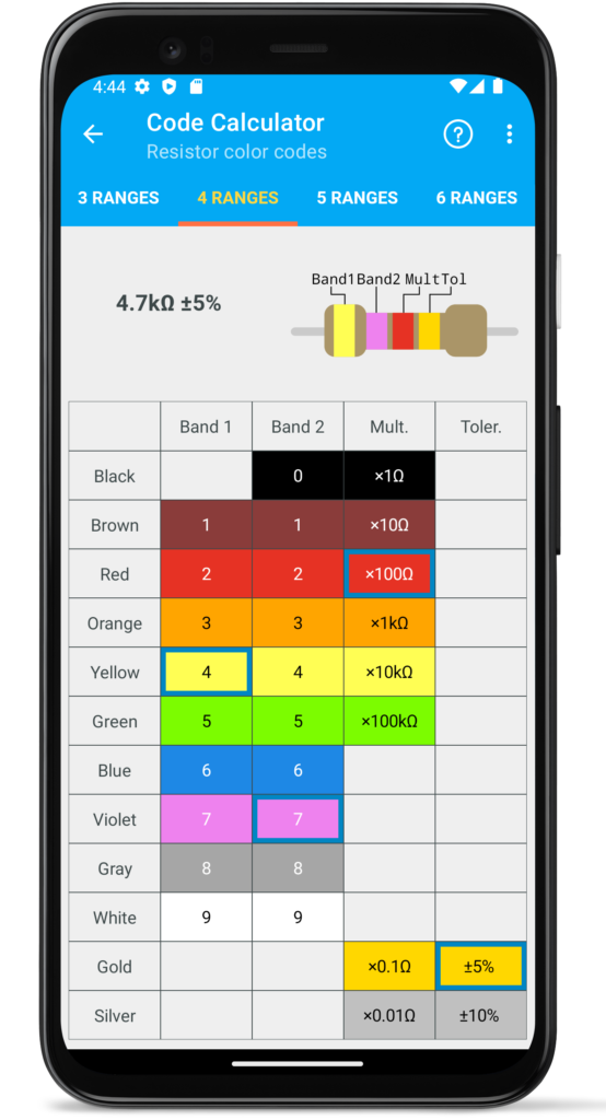
4-band resistor
Four-band color code is the most common option. These resistors have two resistance bands, one multiplier and one tolerance band. These resistors have a tolerance of 5% or 10%.
- Tolerance of 10% corresponds to E12 series;
- Tolerance 5% corresponds to E24 series;
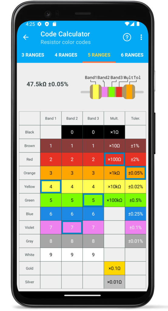
5-band resistor
This is a group of high precision resistors. They have an additional stripe to indicate the third significant digit. Therefore, the first three bars represent significant digits, the fourth bar represents the multiplier, and the fifth bar represents the percentage tolerance.
This group has tolerances of 2%, 1%, 0.5% and less.
- Tolerance of 2% corresponds to E48 series;
- Tolerance of 1% corresponds to E96 series;
- Tolerance of 0.5% and less corresponds to E192 series;
6-band resistor
6-band resistors are usually designed for high-precision resistors with a specific temperature coefficient (TCR). The temperature coefficient of resistance characterises the dependence of electrical resistance on temperature. The initial temperature is considered to be + 25°C. Temperature coefficient is measured in ppm/K.
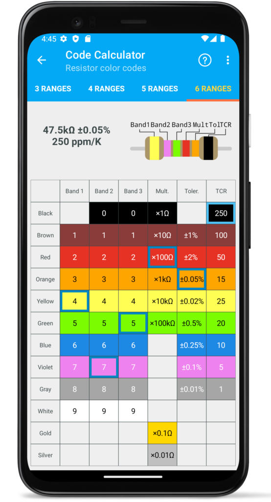
Single black stripe or zero resistance resistor
A resistor with one black stripe is called a zero resistance resistor. It is mainly used as a jumper with the function of connecting conductors on a PCB. The advantage of using a resistor pack is that you can use the same machines to place components on a PCB.
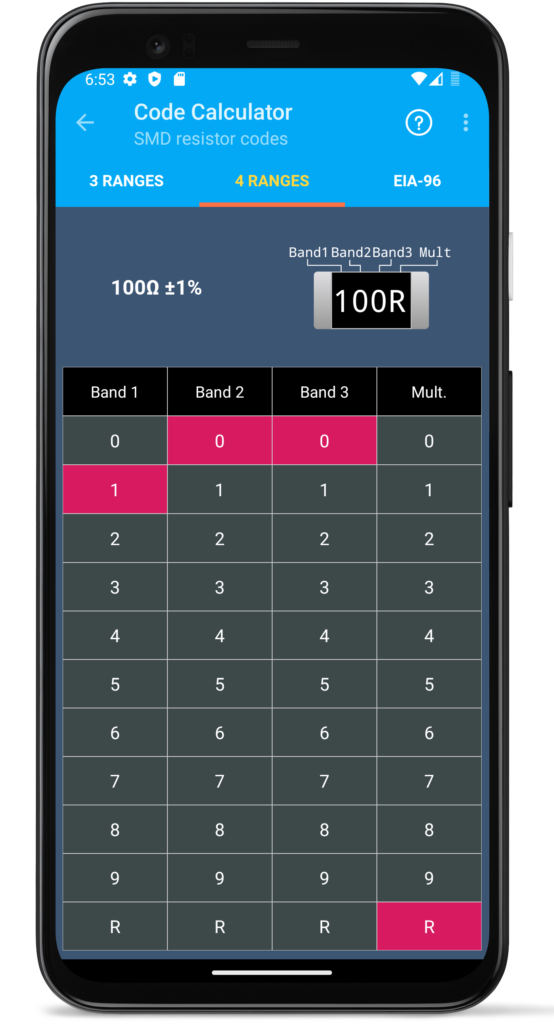
SMD resistor codes
SMD resistor codes page have tree types of standard and EIA-96 precision resistors
SMD resistors have a three- or four-digit code. Also, for precision SMD resistors there is a separate EIA-96 coding system.
3-digit code
Standard Tolerance SMD resistors are labeled with a simple three-digit code. The first two numbers show the meaning in ohms, and the third is a multiplier.
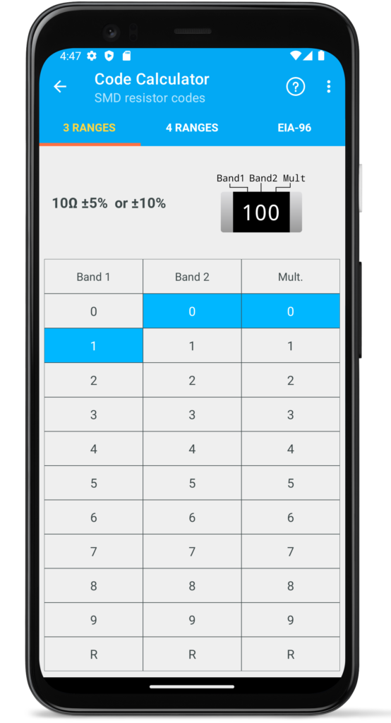
Resistances less than 100Ω may not have a multiplier, the letter is used instead R to indicate the position of the decimal point. These resistors use the series of preferred numbers E12 with 10% tolerance or E24 with 5% tolerance.
Examples of 3-digit code:
- 2R2 = 2.2Ω
- 681 = 68 × 101= 680Ω
- 104 = 10 × 104= 100kΩ
4-digit code
The 4-digit code is used to mark precision SMD resistors. It is similar to the previous system, the only difference is in the number of significant digits: the first three numbers tell us the significant digits, and the fourth will be a factor indicating the power of ten by which three significant digits must be multiplied.
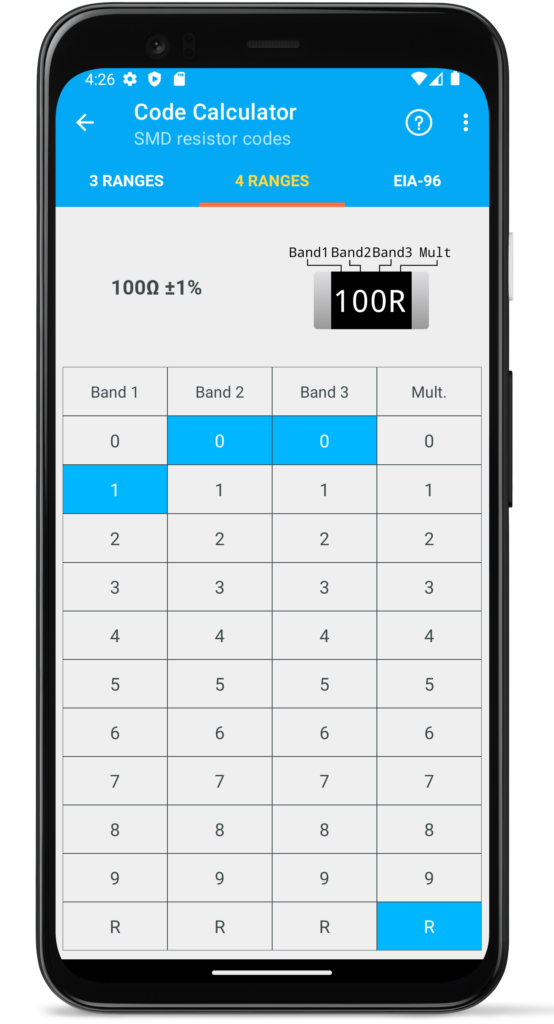
Resistances with value less than 100Ω also denoted by the letter R indicating the position of the decimal point.
These resistors use the series of preferred numbers: E48 (2%), E96 (1%), E192 (< 0.5%).
Examples of 4-digit code:
- 1330 = 133 × 100= 133 Ω
- 7151 = 751 × 101= 7.15kΩ
- 6812 = 681 × 102= 68.1kΩ
EIA-96 Encoding
The EIA-96 coding system is used for precision SMD resistors with a tolerance of 1%. The code consists of 3 symbols: the first 2 digits indicate the coded value of the resistor, and the third character is a letter that indicates the multiplier.
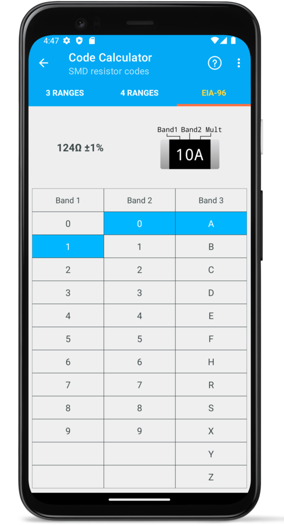
The denomination coding is presented in the table:
| Code | Value | Code | Value | Code | Value | Code | Value |
|---|---|---|---|---|---|---|---|
| 01 | 100 | 25 | 178 | 49 | 316 | 73 | 562 |
| 02 | 102 | 26 | 182 | 50 | 324 | 74 | 576 |
| 03 | 105 | 27 | 187 | 51 | 332 | 75 | 590 |
| 04 | 107 | 28 | 191 | 52 | 340 | 76 | 604 |
| 05 | 110 | 29 | 196 | 53 | 348 | 77 | 619 |
| 06 | 113 | 30 | 200 | 54 | 357 | 78 | 634 |
| 07 | 115 | 31 | 205 | 55 | 365 | 79 | 649 |
| 08 | 118 | 32 | 210 | 56 | 374 | 80 | 665 |
| 09 | 121 | 33 | 215 | 57 | 383 | 81 | 681 |
| 10 | 124 | 34 | 221 | 58 | 392 | 82 | 698 |
| 11 | 127 | 35 | 226 | 59 | 402 | 83 | 715 |
| 12 | 130 | 36 | 232 | 60 | 412 | 84 | 732 |
| 13 | 133 | 37 | 237 | 61 | 422 | 85 | 750 |
| 14 | 137 | 38 | 243 | 62 | 432 | 86 | 768 |
| 15 | 140 | 39 | 249 | 63 | 442 | 87 | 787 |
| 16 | 143 | 40 | 255 | 64 | 453 | 88 | 806 |
| 17 | 147 | 41 | 261 | 65 | 464 | 89 | 825 |
| 18 | 150 | 42 | 267 | 66 | 475 | 90 | 845 |
| 19 | 154 | 43 | 274 | 67 | 487 | 91 | 866 |
| 20 | 158 | 44 | 280 | 68 | 499 | 92 | 887 |
| 21 | 162 | 45 | 287 | 69 | 511 | 93 | 909 |
| 22 | 165 | 46 | 294 | 70 | 523 | 94 | 931 |
| 23 | 169 | 47 | 301 | 71 | 536 | 95 | 953 |
| 24 | 174 | 48 | 309 | 72 | 549 | 96 | 976 |
The resistor multiplier is encoded with letters:
| Code | Multiplier |
| A | 1 |
| B | 10 |
| C | 100 |
| D | 1000 |
| E | 10000 |
| F | 100000 |
| H | 10 |
| R | 0.01 |
| S | 0.1 |
| X | 0.1 |
| Y | 0.01 |
| Z | 0.001 |
Please note that some multipliers can be encoded with two different letters.
Examples of EIA-96 coded resistors
- 14X = 137 × 0.1 = 13.7Ω
- 94C = 931 × 100 = 93.1kΩ
Ceramic capacitor codes
On ceramic disk capacitors, the code can be contained 1-4 characters.
1-2 symbols
If the capacitor has only one or two symbols, this means that there is no multiplier and the capacitor simply indicates the capacitance in picofarads. For example, 15 – then its value is 15pF.
3 symbols
The first two symbols indicate the capacitance of the capacitor, and the third number is the multiplier.
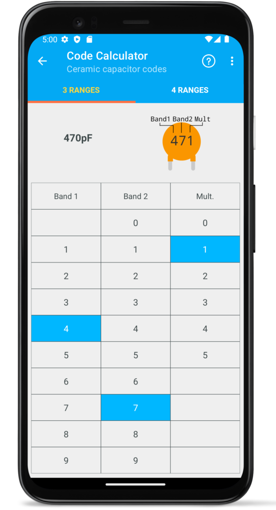
When the first two numbers are multiplied by a factor, the resulting value is the capacitor value in picofarads. For example:
- 220 = 22 × 100= 22pF
- 681 = 52 × 101= 680pF
- 472 = 47 × 102= 4700pF = 47nF
- 104 = 10 × 104= 100000pF = 100nF = 0.1 μF
Sometimes the letters p, n, µ are present on the capacitors. They can be used as decimal separator, for example:
- 22p = 22pF
- n47 = 0.47nF
- 4n7 = 4.7nF
- μ22 = 0.22μF
4 symbols
An additional fourth character is a letter denoting the permissible tolerance of the capacitor’s capacitance.
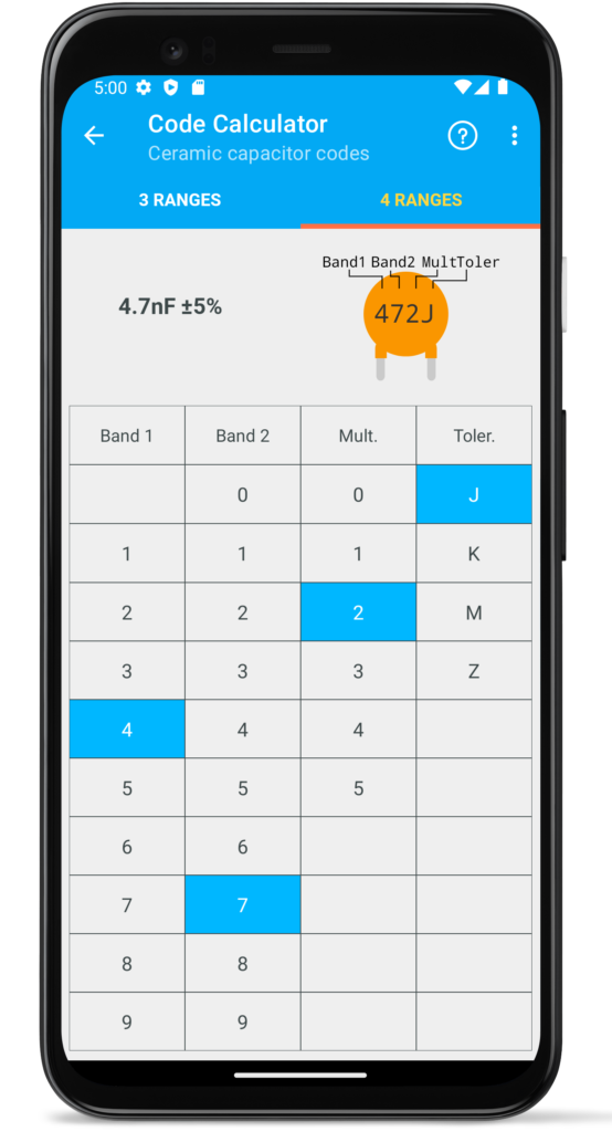
Capacitor tolerance coding is shown in the table:
| A | ±0,05pF |
| B | ±0,1pF |
| C | ±0,25pF |
| D | ±0,5pF |
| F | ±1,0% |
| G | ±2,0% |
| H | ±2,5% |
| J | ±5,0% |
| K | ±10% |
| L | ±15% |
| M | ±20 |
| N | ±30% |
| P | -0…+100% |
| Q | -10…+30% |
| S | -20…+50% |
| T | -0…+50% |
| U | -0…+75% |
| W | -10…+100% |
| Y | -20…+5% |
| Z | -20…+80% |
The letter indicating the tolerance is indicated after the value of the nominal capacity: 22nK, 220nM, 470nJ. Tolerances A, B, C, D apply to capacitors of 15pF or less. Mostly in household appliances, capacitors with a tolerance of J, K, M, Z are widely used.
Examples:
- 22pK = 22pF ±10%
- n47J = 0.47nF ±5%
- μ22M = 0.22μF ±20%
On ceramic capacitors, the value of the operating voltage can be indicated after the capacity and tolerance. This is an optional parameter, set mainly on high-voltage capacitors. Typically, voltage is indicated in volts by the letter V. For example, 16V, 250V, 1kV.
Some manufacturers may use denominations that are not included in the standard — e.g. 5pF.
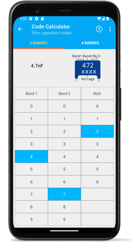
Film capacitor codes
On ceramic disk capacitors, the code can be contained 3 or 4 characters (without voltage code).
3 symbols
The first two characters indicate the capacitance, and the third number is the multiplier. The resulting value is the capacitor value in picofarads. Examples:
- 473 = 47 × 103= 47000pF = 47nF
- 104 = 10 × 104= 100000pF = 100nF = 0.1 μF
Sometimes, the letters p, n, µ are present on the capacitors. They can be used as decimal separator, for example:
- 22p = 22pF
- n47 = 0.47nF
- 4n7 = 4.7nF
- μ22 = 0.22μF
4 symbols
An additional fourth character is a letter denoting the permissible deviation of the capacitor’s capacitance.
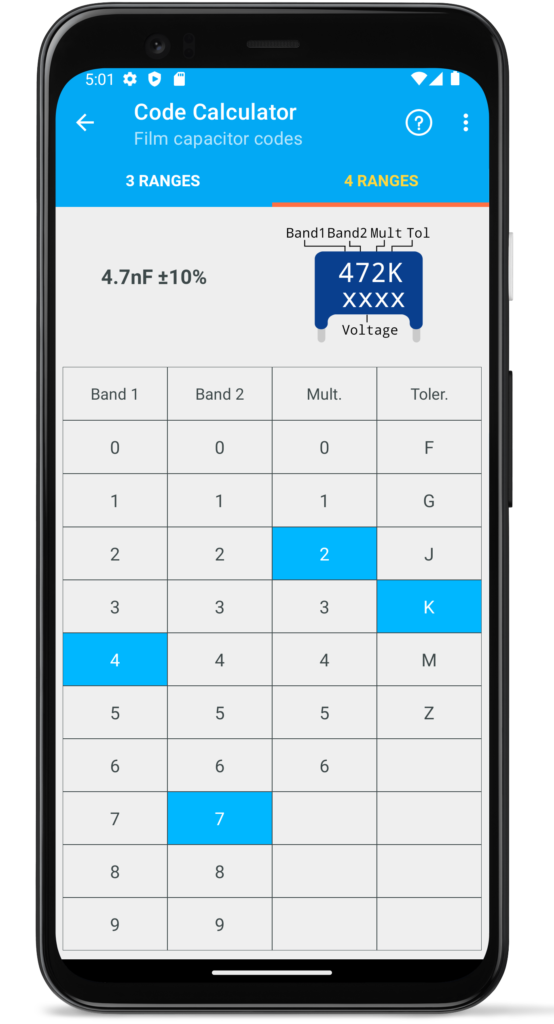
Capacitor tolerance coding is shown in the following table:
| Code | Tolerance |
| F | ±1,0% |
| G | ±2,0% |
| H | ±2,5% |
| J | ±5,0% |
| K | ±10% |
| L | ±15% |
| M | ±20% |
| Z | -20…+80% |
The letter denoting the tolerance is indicated after the value of the nominal capacity: 22nK, 220nM, 470nJ. Basically, in household equipment, capacitors with a tolerance of H, M, J, K are widely used. Tolerances with A, B, C, D symbols are used for capacitors with a capacity of 15pF and less only. Examples:
- 22pK = 22pF ±10%
- n47J = 0.47nF ±5%
- μ22M = 0.22μF ±20%
Voltage code
On the capacitor, the value of the permissible operating voltage is indicated after the nominal capacity and the tolerance. There are two options:
- The voltage is indicated in volts with the letter V. For example, 16V, 250V, 1kV.
- Use EIA coding
The EIA coding for capacitor’s voltage is shown in the table:
| Code | Voltage |
| 0G | 4.0V |
| 0L | 5.5V |
| 0J | 6.3V |
| 1A | 10V |
| 1C | 16V |
| 1E | 25V |
| 1H | 50V |
| 1J | 63V |
| 0k | 80V |
| 2A | 100V |
| 2Q | 110V |
| 2B | 125V |
| 2C | 160V |
| 2Z | 180V |
| 2D | 200V |
| 2P | 220V |
| 2E | 250V |
| 2F | 315V |
| 2V | 350V |
| 2G | 400V |
| 2W | 240V |
Film capacitors colour codes
This color code for film capacitors (Tropical fish) has limited use for film capacitors. These capacitors are not available now, but they can be found in old electronic equipment.
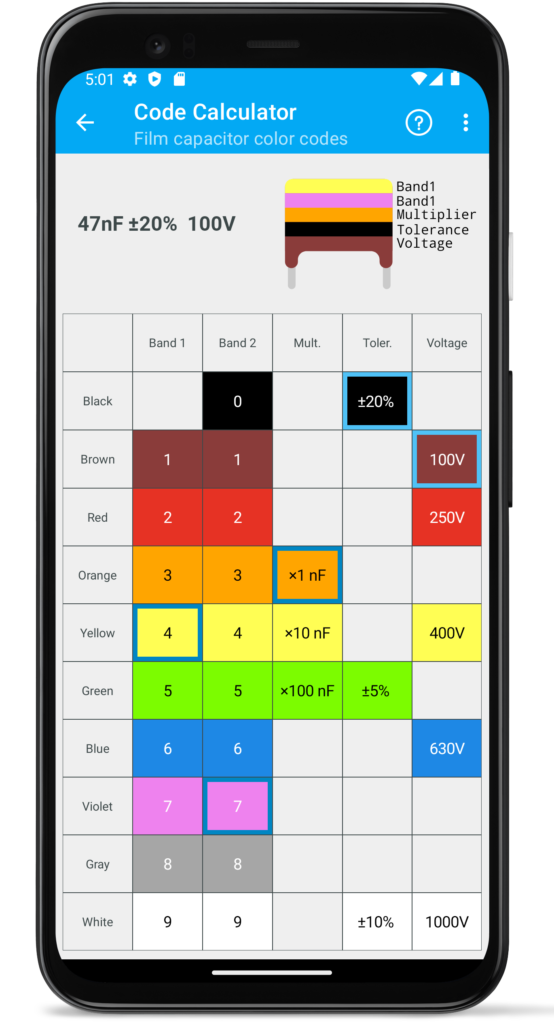
Standard ratings, depending on accuracy, correspond to series E6, E12 and E24.
These capacitors have 5 bands, the first band is counted from the top of capacitor:
- 1.2 line – capacity value
- 3 line – multiplier
- 4 line – precision
- 5 line – voltage
Note that some combinations of stripes can cause 2 adjacent stripes to be the same color, so it looks like there are 4 stripes on the capacitor, but this stripe will be wider than the rest. Consider this when determining capacity.
SMD Tantalum electrolytic capacitors codes
The simplest tantalum capacitor coding system directly shows the capacitance value, for example 22 µF.
Another marking option is a three-digit code: The first two digits show the capacity in picofarads, the third is the multiplier. For example:
- 225 = 22 × 105 = 2200000pF = 2.2μF
- 476 = 47 × 106 = 47000000pF = 47μF
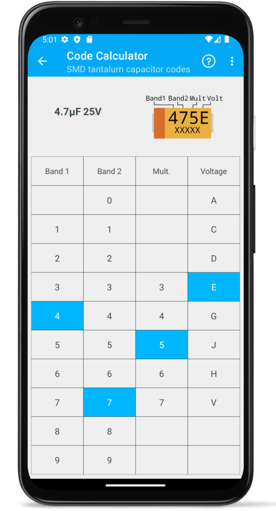
The operating voltage of the capacitor can be indicated in volts, for example, 25V. Letter encoding can also be used.
Voltage coding options are presented in the table:
| Code | Voltage |
| e | 2.5V |
| G | 4V |
| J | 6.3V |
| A | 10V |
| C | 16V |
| D | 20V |
| E | 25V |
| V | 35V |
| H | 50V |
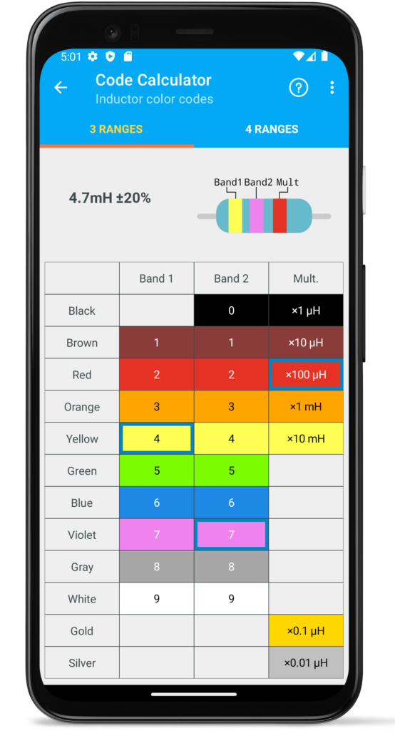
Inductor color codes
Inductors color coded usually contains with 3 or 4 stripes.
3 stripes
The definition of inductance is similar to the color coding of resistors. The first two bands define the inductance value in µH. The third bar is a multiplier.
The tolerance of such inductors is 20% and the range of values corresponds to E6 series.
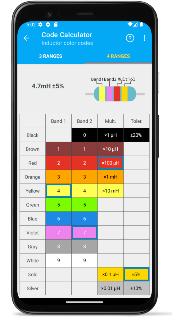
4 stripes
Additional bandwidth on inductors adds tolerance. Typically, inductors with additional stripe have tolerances of 5% (gold stripe) or 10% (silver stripe).
- 10% tolerance corresponds to E12 series;
- 5% tolerance corresponds to E24 series;
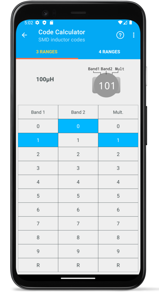
SMD inductor color codes
SMD inductors coded usually contains with 3 or 4 symbols.
3 symbols
The first two characters indicate the inductance, and the third number is the multiplier. The resulting value is the capacitor value in microhenry. For example:
- 121 = 12 × 101= 120μH
- 103 = 10 × 103= 10000μH = 10mH
These inductances have a tolerance of 20%.
4 symbols
Precision inductors have a fourth character to indicate tolerance
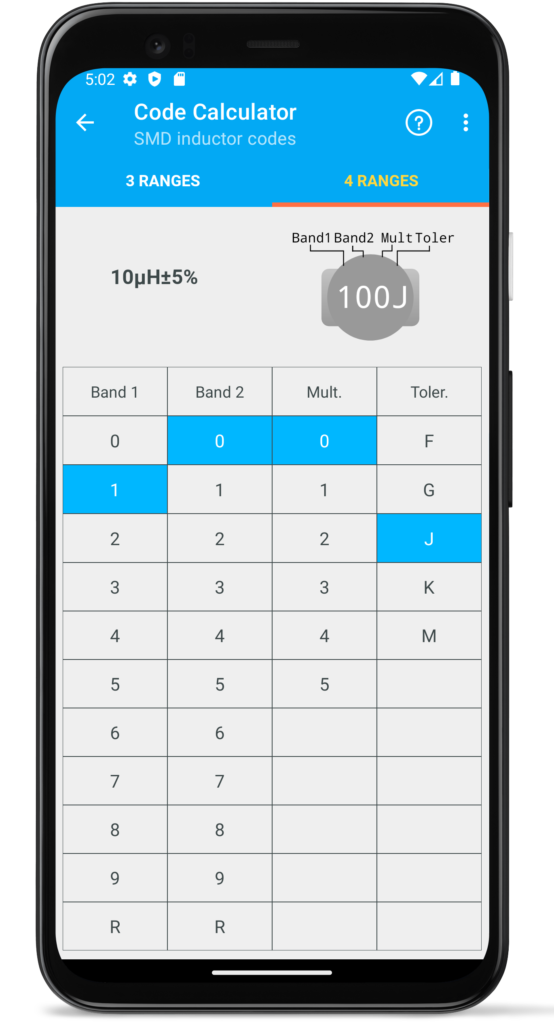
Tolerances for inductors are presented in the table.
| Code | Tolerance % |
| F | ±1,0% |
| G | ±2,0% |
| J | ±5,0% |
| K | ±10% |
| M | ±20% |
For example:
- 100J = 10 × 100 = 10μH, 5%
- 221K = 22 × 101 = 220μF, 10%
Helps
Every component calculators have reference page contains a detailed description to help you read component codes:
Settings
Settings page contains two options: language and theme.
App languages
The application language is independent of the system language. That is, if the system language is English, in the application you can set other language from list, for example, Spanish.
Currently, this application is translated into 6 languages, but new languages will be added in future versions.

App themes
Depending on the user’s preferences, the application can be displayed in light or dark theme. The application has 3 options:
- System default
- Light
- Dark

When you set the systems default option, the application will use the theme installed on the device. The other options set a theme independent of the system theme. Dark theme can also be installed on older versions of Android that do not have theme switching.